
There are over hundred of weather sondes sent over the Europe each
day from different locations for weather forecasts and other scientific
or military purposes. Weather sondes are expendable electronic devices
to measure wind speed, air temperature, humidity and pressure. Sondes
attached to a balloon filled with hydrogen or helium ascent up into the
stratosphere where the balloon bursts and the sonde falls down back to
earth with a parachute.
Weather sondes transmit collected information
over the radio within the 400-407 MHz range. GPS coordinates are
transmitted too which makes it possible to trace sondes. Some amateur
radio operators have built tracking radio stations that automatically receive
signals from radiosondes, decode the GPS position and other telemetry
and submit this information on internet where it is available to
anybody. Here are some servers for tracking of radiosondes:
Note: I’m not affiliated with any of these servers and can’t answer any related questions
Taking into account the amount of radiosondes sent each day they are
considered as electronic waste that needs to be removed from the
environment. The weather/meteorological services that launch weather
sondes never try to reclaim them because it would be too expensive (see
the note below), so some people have developed a hobby to hunt the
sondes.
Note: one can get paid for delivering some expensive sondes for ozone measurements back to the weather station that launches them
Hunting radiosondes
Hunting of radiosondes is possible due to the fact that they keep sending signals even after the landing. There’s a feature called - Burst Kill Timer (BKT). The weather services are only interested in information that sondes are sending during the ascend. When the balloon bursts the sonde is not tracked any longer and the data it sends is discarded. As far as sondes are sent twice a day it should be ensured that they never transmit longer than 12 hours to avoid any interference. And this is what the BKT is for - after the burst a timer is started which switches the sonde off after pre-programmed amount of time. I think that there’s no a single standard for the amount of time for the BKT and each weather service could pre-program any number but I believe that they use the maximum allowed time (around 8.5 hours after the balloon burst) to ease the ‘search and dispose’ operation for the hunters.
Why would people hunt radiosondes?
Well, it’s a good question. Different people have different motives I’d say:
- some do hunt expensive sondes for money. Those focke wulfs are usually good equipped and go hunting in their Messerschmitts, oh, I mean Volkswagens (Farvegnugen and Volkswagen, their favorite singer is Nina Hagen) and it’s really difficult to beat them at hunting because they are on the spot minutes after landing or even during the landing.
- some do it just for fun. Those people usually go on foot or with a bike, so that they could spice up their sport activity to make it even more entertaining. Such people are also often attracted by the technical challenges this activity offer.
- some are really obsessed and for them sonde hunting is the sport activity itself. Such people could get really mad if somebody else would grab “their” sonde first. Examples? Oh, I have some but I won’t even bother to put them here
- some people do re-purpose radiosonde’s hardware by reprogramming them. Some examples:Firmware for RS41 for HAM use
GPS Mouse from DFM06
Note it’s forbidden to transmit without proper license! So if you switch on a radiosonde that you found somewhere you should know what you’re doing!
Sonde types
There are several different sondes types but the most commonly used is RS41 sonde by Vaisala. These sondes are relatively cheap and also very versatile. There are variants with a daughter card to measure air pressure and it is also possible to attach an ozone module. I’ve heard that weather and meteorological services are using these sondes because it is possible to automate sonde’s launches. Military usually launch sondes manually. Much rarer in my region are RS92, DFM06/09, M10 and SRC-C50 sondes. There’s a good technical description of different sondes on this site
But how do people hunt radiosondes?
Good question - that’s the reason why I wrote this article, because I wanted to explain my approach. But before I start with it, it’s a good idea to explore existing ones
Hunting bare hands
The cheapest way to find a sonde is to use aforementioned tracking internet sites and when a sonde lands somewhere near your QTH (a fancy way of saying Home) go there and try to find it. This method is also called - cold search. I found couple of sondes using only this method. Effectiveness of this method is rather low. The tracking sites usually never give you exact GPS coordinates of the landing point. Normally the last logged position is several hundred meters above the ground. Taking into account the wind speed the searching radius could be really big - from several hundreds meters to kilometers. In rare occasions when a sonde lands close to a tracking station one could get the exact coordinates on the ground. Well with the exact I mean - with the accuracy of the GPS receiver which is ±20 meters I believe. And in a forest it is really difficult to find a sonde even within 20 meters searching radius.
Hunting with a directional antenna and a power meter
This technique requires some investments and some understanding of radio communication theory but isn’t actually really difficult. One would need a directional antenna and a signal power meter.
As a power meter one could use a Handheld RF Spectrum Analyzers like
‘RF Explorer’ or one could use a real Handheld radios like a cheap
Baofeng. These radios have a so called S-Meter that shows the signal
strength. I never had such devices so I can’t say more.
One could of course build its own power meter like Wetter-Sonden-Tracker by OE3AJC
Alternatively one could use a so called RTL-SDR dongle and a software like GQRX or SDR# that shows the signal strength and its spectrogram (I’ll get to this later). I have used this method too with my Yagi-Uda antenna in cases when I couldn’t find live sonde even knowing its GPS coordinates:

Hunting using only a directional antenna and a power meter could be
fun. Big plus is that any type of sondes can be tracked this way. One
negative side is that sondes do not transmit forever and there might be not enough time to locate the signal source. Another negative side is that directional antennas for 400 MHz could be bulky
and do not perfectly fit for hunting in complex terrains. Try to move in a
corn field with something like OE3AJC has built and you’ll find that
it’s no fun. Or take a look what monster antenna this guy has. Does he really walk around with it?
By the way it’s not absolutely necessary to have an antenna designed
for 400 MHz. By sacrificing some gain one could use an off-band antenna
designed for higher frequencies which could be a lot smaller.
Antenna design is a different huge topic which I won’t
cover here but I’ll show my stationary and my Jagi-Uda antennas I built from scrap.
A stationary ground plane antenna
At home I'm using a very simple yet effective ground plane antenna built from scrap. Impedance matching is done by adjusting the radials's angle. It is also very easy to assemble/disassemble this antenna for transportation. It is still in the queue to get me a Vector Network Analyser to fine tune it but even now I can receive and decode signals from sondes that are more than 300 km away
As the base a so called 'N-Type Straight Solder Jack' is used.
A mobile Yagi-Uda Antenna built from scrap
Very often happen that the sonde lands in a forest and despite the
fact that I can receive its signal and decode coordinates I still
cannot locate it. In this situation the only solution is to use a
directional antenna to locate the radio signal source. There are numerous
possible solution one could find on the internet but an antenna for 400
MHz is relatively big and I needed a mobile solution because I only hunt
on foot or with my bike, so the antenna should fit into my backpack and
not be broken or bent. So I took a so called ‘rabbit ear’ dipole
antenna from an old TV, replaced telescopic arms with 2.5mm copper wire and
put it on a boom with the reflector and two parasitic elements (also called directors) cut from
the same copper wire. To connect the elements to the boom I cut 20x40
aluminium profile. Rubber bands that holds everything on the boom are cut from a
balloon rest. Reflector and directors are stored inside of the
boom:


Additionally I bought couple of adapters to convert TV aerial
plug to SMA.
The lengths of the elements and the distance between them can be calculated using any ‘Yagi antenna calculator’ on the internet.
If I didn’t have the ‘rabbit ear’ antennas I’d probably went for ‘Moxon antenna’. This antenna is very simple and doesn’t require any impedance matching. But honestly, sacrificing some gain the impedance matching could also be skipped for any other antenna type.
Hunting using software decoders
This is the most popular method nowadays because it doesn’t require any expensive hardware. One would need a laptop and a so called RTL-SDR dongle. Those dongles are DVB-T USB radio receivers based on RTL2832U and R820T2/R820T chips. The DVB-T standard is not used anymore, so those dongles are sold very cheap now, like 15 Euro on Amazon.
There are different more expensive modifications available that offer stable temperature compensated clock source TCXO, zero PPM and stuff. This isn’t really necessary and I’m only using cheapest dongles I could find. Important to check that the dongle is really based on RTL2832U and R820T2/R820T chips. Anything else isn’t important. I’ve read that R820T2 chips provide better SNR ratio but all dongles I have are equipped with R820T chips, still I’m able to receive and decode sondes that are more than 300 km away.
Small stock antenna doesn’t perfectly fit to the sonde’s frequency
range but it’s good enough for radiosonde hunting. This antenna needs to
be improved a bit first. Basically one has to remove the sticker at the
bottom and make sure that the braid is connected to the metal foot
(check also this
out). This antenna also needs a ground plane - any metal plane where the
antenna can be put onto. Usually I’d go as close as possible to the
landing point until I’d hear a weak noise level change. Then I'd look for anything metal and if I couldn't find anything then I’d pull
out a metal plane from my backpack, put the stock antenna onto it and
then I could receive the signal strong enough to decode it

There are basically two stages of signal processing we are interested in:
- Demodulation
- Decoding
Demodulation
Simply put demodulation means that the input radio signal is
converted into a form that decoders understand. There are couple of well
known software programs with UI that can help with demodulation:- SDR# (for Windows)
- GQRX (for Linux)
- rtl_fm program belongs to the rtl-sdr package available for different Linux distributions
Decoders
Demodulated signal usually in a form of an audio stream is then sent
to a decoder. There are several programs that are used to decode the
audio stream:- SondeMonitor is a Windows only shareware program. Here is a tutorial of decoding a radiosonde signal using SDR# and SondeMonitor combo.
- RS41 Tracker is a Windows only freeware program. Can be used in combination with SDR# too. This program can only be used to decode signals from RS41 sondes.
- Zilog decoders. A person with the nickname Zilog80 has developed a set
of decoders for different rasiosondes types. His repo can be found here.
His repo is a bit messy, so I have cloned only the needed parts here. To use it with GQRX one would tune GQRX to the desired frequency,
select Narrow FM, select proper bandwidth (6 KHz for RS41), select proper
gain (Automatic or Hardware AGC works good) and then select UDP. After
that decoded signal will be sent over UDP as an audio stream.
Here is an example of receiving and decoding such stream with the rs41mod decoder:
The same using the rtl_fm instead of the GQRX:nc -lu6 -p 7355 | sox -t raw -esigned-integer -b 16 -r 48000 - -b 8 -c 1 -t wav - highpass 10 gain +5 | ./rs41mod --json --ecc --crc sox WARN wav: Length in output .wav header will be wrong since can't seek to fix it sample_rate: 48000 bits : 8 channels : 1 [ 7041] (P3320196) Sun 2020-05-17 18:24:42.001 lat: 49.20829 lon: 12.82097 alt: 9884.73 vH: 16.0 D: 128.2 vV: -14.5 (19) { "type": "RS41", "frame": 7041, "id": "P3320196", "datetime": "2020-05-17T18:24:42.001Z", "lat": 49.20829, "lon": 12.82097, "alt": 9884.73114, "vel_h": 15.95571, "heading": 128.24817, "vel_v": -14.53831, "sats": 8, "bt": 65535, "batt": 2.60, "subtype": "RS41" }
the only difference is that I added a low pass filter to improve decoder sensitivity and a multiplexer with output to aplay to hear the sound.rtl_fm -f 402700000 -s 48000 -p 35 | sox -t raw -esigned-integer -b 16 -r 48000 - -b 8 -c 1 -t wav - lowpass 3000 highpass 10 gain 5 | tee >(aplay -r 48000 -f S8 -t wav -c 1 -B 500000) | ./rs41mod --json --ecc --crc
- radiosonde_auto_rx is based on Zilog’s decoders and used to automatically tune, receive and decode radiosondes.
- dxlAPRS. This software is a set of tools to operate APRS. According the description it can also be used to receive and decode sonde’s signals.
- sondefinder is a software written for Raspberry Pi. I don’t know if it is possible to use the software with a normal laptop because I honestly don’t see a reason why would anyone want to build a keyboard-less Raspberry Pi based laptop.

Hunting using specialized hardware
-
TTGO LoRa ESP32 Hardware based approach.
This one is really nice approach because they are using available
hardware module and they also have an App to control it. But if I’m not
mistaken they are only supporting RS41 and DFM06/09 sondes.
-
Rolf’s RA approach.
Really nice design. I’ve seen it live and it looks really good. A
smartphone App controls the hardware and shows hunter’s and sonde’s
position on a map. Maybe he will upload some screenshots of his App too.
Please let me know if you know any other option
My SDR based design
Before I start describing my design I want to outline some problems with the aforementioned solutions:
- Windows only software - bummer, I’m not using Windows
- Hardware solutions like TTGO LoRa or Rolf’s RA require specialized hardware. I could build Rolf’s hardware principally but it’d be very expensive and time consuming. Additionally if it would broke once then I’d have a problem that I couldn’t solve fast. LoRa module solution is nice but I can’t hear the signal I’m tuned to and its software is limited.
- No specialized hardware is required. It should work on any hardware where I can install Linux.
- I really like to hear the signal I’m tuned to. Usually I ride my bike close to the landing point until I hear the sonde signal over my bluetooth headset.
- Support for any sonde type for which a software decoder is available.
- It should work on any headless Linux system without any graphics subsystem. This means that I can’t use GQRX for demodulation. rtl_fm could be used with such systems but I can’t control it remotely, e.g. change tuner frequency.
- It should be possible to have all information I need on a smartphone.
What do I have?
I have an RTL-SDR dongle and Zilog’s decoders that I can compile for specific CPU architecture and transform/filter their output if needed. If any other decoder would be needed I could compile it as a separate module and include it into my design easily.
What’s missing?
- Receiver
- Demodulator
- Controller
Receiver
Receiver is needed to get the signal (or IQ samples) from the RTL-SDR dongle to feed the demodulator. Receiver is controlled by the controller to tune it to a specific frequency and set other parameters.
The perfect fit here is of course the rtl_tcp daemon. The daemon listens on a specific TCP port for clients and when one connects provides IQ samples over that TCP port. rtl_tcp daemon is part of the rtl-sdr package. The rtl-sdr package is available on many different Linux distributions, so there is no need to compile or cross compile it. Install it on a Debian based distribution using:
sudo apt install rtl-sdr
Controller
I have described previously a very simple bash script I wrote to control the rtl_tcp daemon and get IQ samples from it here . I have extended that script a bit to make it possible to interactively change receiver parameters:
# part of the rtlclient2.sh script

tail -f "$controlfile" | while read LINE
do
  case "$LINE" in
    freq*) set_frequency "${LINE#freq }" ;;
    srate*) set_sample_rate "${LINE#srate }" ;;
    gain*) set_gain "${LINE#gain }" ;;
    ppm*) set_ppm "${LINE#ppm }" ;;
    *) ;;
  esac
done | nc $address $port
Demodulator
Demodulator performs the following basic operations with the input IQ samples stream:
- Decimation - tuner sampling frequency is translated to the decoder input frequency. If for example tuner sampling frequency is 960000 Hz and decoder input frequency is 48000 Hz then decimation factor should be 960000/48000 = 20. So after decimation there will be 20 times less samples per second.
- Filtering - anything that does not belong to the sonde signal bandwidth is filtered out.
- Quadrature FM demodulation - performs FM demodulation.
Here is a part of the receivesonde.sh script:
log_power()
{
  (
    ./csdr convert_u8_f | \
    ./csdr fft_cc $SCAN_BINS $((TUNER_SAMPLE_RATE/(SCAN_UPDATE_RATE*SCAN_AVERAGE_TIMES))) | \
    ./csdr logaveragepower_cf -70 $SCAN_BINS $SCAN_AVERAGE_TIMES | \
    ./csdr fft_exchange_sides_ff $SCAN_BINS  |
    ./csdr dump_f | tr ' ' '\n' | \
    awk -v bins=$SCAN_BINS '{printf("%.1f ",$0);if(0==(NR%bins)){printf("\n")};fflush()}' | \
    awk -v bins="$SCAN_BINS" -v sr="$TUNER_SAMPLE_RATE" '{printf("{\"response_type\":\"log_power\",\"samplerate\":%d,\"result\":\"%s\"}\n", sr, $0);fflush()}'
  ) &> /dev/stdout | grep --line-buffered -E '^{' | \
    while read LINE; do
      (flock 200; echo "$LINE") 200>$MUTEX_LOCK_FILE
    done
}

decode_sonde()
{
  (
    ./csdr convert_u8_f | \
    ./csdr fir_decimate_cc $DECIMATE 0.005 HAMMING | \
    ./csdr bandpass_fir_fft_cc --fifo $BANDPASS_FILTER_FIFO 0.02 | \
    ./csdr fmdemod_quadri_cf | ./csdr limit_ff | ./csdr convert_f_s16 | \
    sox -t raw -esigned-integer -b 16 -r $DEMODULATOR_OUTPUT_FREQ - -b 8 -c 1 -t wav - highpass 10 gain +5 | \
    tee >(./c50dft -d1 --json /dev/stdin > /dev/stderr) | \
    tee >(./dfm09mod --ecc --json -vv /dev/stdin > /dev/stderr) | \
    tee >(./dfm09mod --ecc --json -i /dev/stdin > /dev/stderr) | \
    tee >(./rs41mod --ecc --crc --json -vv /dev/stdin > /dev/stderr) | \
    tee >(./rs92mod -e "$EPHEM_FILE" --crc --ecc --json /dev/stdin > /dev/stderr) | \
    aplay -r 48000 -f S8 -t wav -c 1 -B 500000 &> /dev/null
  ) &>/dev/stdout | grep --line-buffered -E '^{' | jq --unbuffered -rcM '. + {"response_type":"sonde"}' | \
    while read LINE; do
      (flock 200; echo "$LINE") 200>$MUTEX_LOCK_FILE
    done
}

[[ -p "$BANDPASS_FILTER_FIFO" ]] || mkfifo "$BANDPASS_FILTER_FIFO"
(calc_bandpass_params $SONDE_SIGNAL_BANDWIDTH $DEMODULATOR_OUTPUT_FREQ > "$BANDPASS_FILTER_FIFO") &
(./rtlclient2.sh -P $DONGLE_PPM -f $INPUT_FREQ -g $TUNER_GAIN -s $TUNER_SAMPLE_RATE - | tee >(log_power >/dev/stderr) | decode_sonde)
What is happening here? I’m connecting to the rtl_tcp over the rltclient2.sh script and then multiplexing IQ samples into the log_power and decode_sonde functions. So I’m calculating the FFT and decoding the signal at the same time. As you can see I also start all the decoders at the same time by multiplexing demodulator output. Also I start aplay to hear the signal.
Output of the receivesonde.sh looks like this:
{"response_type":"log_power","samplerate":960000,"result":"-68.2 -69.4 -68.1 -68.5 ... "}
{"response_type":"log_power","samplerate":960000,"result":"-61.7 -60.0 -60.5 -58.7 ... "}
{"response_type":"log_power","samplerate":960000,"result":"-59.0 -58.9 -61.7 -61.0 ... "}
{"response_type":"log_power","samplerate":960000,"result":"-63.2 -60.5 -60.0 -61.3 ... "}
{"response_type":"log_power","samplerate":960000,"result":"-59.1 -59.4 -58.9 -57.8 ... "}
{"type":"RS41","frame":7278,"id":"R2830515","datetime":"2020-05-24T06:21:19.001Z","lat":48.03975,"lon":12.02263,"alt":24675.42637,"vel_h":9.1559,"heading":266.50958,"vel_v":-30.42903,"sats":8,"bt":65535,"batt":2.7,"subtype":"RS41","response_type":"sonde"}
{"response_type":"log_power","samplerate":960000,"result":"-57.5 -59.7 -60.2 -57.4 ... "}
{"response_type":"log_power","samplerate":960000,"result":"-60.3 -59.4 -60.0 -59.7 ... "}
{"response_type":"log_power","samplerate":960000,"result":"-60.5 -61.1 -62.5 -60.8 ... "}
{"response_type":"log_power","samplerate":960000,"result":"-57.7 -59.0 -59.7 -60.0 ... "}
{"type":"RS41","frame":7279,"id":"R2830515","datetime":"2020-05-24T06:21:20.001Z","lat":48.03975,"lon":12.0225,"alt":24644.68235,"vel_h":10.19232,"heading":267.10627,"vel_v":-31.69135,"sats":9,"bt":65535,"batt":2.6,"subtype":"RS41","response_type":"sonde"}
Rather complicated bandpass filter logic is needed because different sondes types use different bandwidths. To decode RS41 sondes 6 kHz (in complex space) bandpass filter should be applied but 20 kHz for SRC-C50 or M10 sondes. One could of course apply the maximum possible bandwidth for all sondes but it would reduce decoder sensitivity because there would be more noise left.
When the script starts the following two control files are created:
- a bandpass filter fifo to control the bandwidth filter
- a control file to control the tuner
Now, with only two scripts ( receivesonde.sh and rtlclient2.sh) I’m able to receive, measure signal power level, demodulate and decode sonde’s signals.
EDIT 28.07.2020: the bandpass filter logic is not needed and is removed. Actually after fir_decimate_cc I can multiplex output and start particular decoders with different bandpass filter applied. So for example c50dft amd m10mod decoders will be started with 9600 Hz bandpass filter and the rest with 3000 Hz. Very easy solution that reduces complexity tremendously.
Usage examples:
- Decode a sonde at 402.3 MHz with tuner sampling rate set to 960000, signal bandwidth 3 kHz and dongle PPM set to 35.
Power level measurements are filtered out.pgrep -x rtl_tcp || rtl_tcp -a 127.0.0.1 & sleep 1 ./receivesonde.sh -f 402300000 -s 960000 -p 35 -b 3000 &>/dev/stdout | \ jq --unbuffered -rc 'select(.lat)'
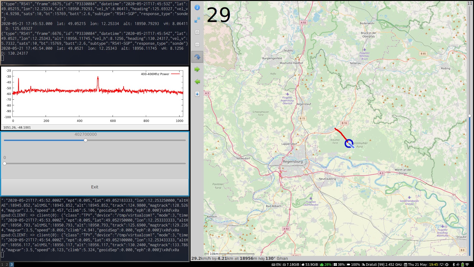
- The same as above but also plot sonde’s position using foxtrotgps software and showing power level
This one is relatively complex example. Output of the receivesonde.sh is multiplexed and filtered to feed the foxtrotgps with data and also feed gnuplotblock.sh script to show power level in real time.
pgrep -x rtl_tcp || rtl_tcp -a 127.0.0.1 &
[ -L "/tmp/virtualcom0" ] || ./vp1.sh &

sleep 1

./receivesonde.sh -f 402300000 -s 960000 -p 35 -b 3000 &>/dev/stdout | \
  tee >(grep --line-buffered datetime|sed -nur 's/(.*datetime":)([^\.]+)....(.*)/\1\2\3/p' - | tee /dev/stderr | \
        jq --unbuffered -rc 'select(.lat)|[.datetime, .lat, .lon, .alt, .vel_h, .heading]|"\(.[0]|strptime("%Y-%m-%dT%H:%M:%SZ")|strftime("%Y-%m-%d %H:%M:%S.000"))  lat: \(.[1])  lon: \(.[2])  alt: \(.[3])  vH: \(.[4])  D: \(.[5])"' | \
        tee /dev/stderr | \
        ~/sondereceive/pos2nmea.pl 2>/dev/null >/tmp/virtualcom0) | \
  jq -rc 'select(.samplerate).result' | awk '{printf("%s", $0);fflush()}' | tr ' ' '\n' | \
  awk '{printf("%d %.1f\n",(NR-1)%1024,$0);if(0==(NR%1024)){printf("\n")};fflush()}' | \
  ~/bin/gp/gnuplotblock.sh "0:1023;-100:-20" "400-406Mhz Power;l lw 2;red;xy"
Description on how to use foxtrotgps can be found here. But it is somewhat over-complicated. So here is my version of vp1.sh to create two virtual COM ports:
#!/bin/bash
# vp1.sh

echo "Creating Virtual Com Port: 0 and 1"

vcpath='/tmp'
socat -d -d pty,link=${vcpath}/virtualcom0,raw,echo=0 pty,link=${vcpath}/virtualcom1,raw,b4800,echo=0 &
socatpid=$!
echo "socat pid=$socatpid"
sleep 2

trap "kill $socatpid &>/dev/null; exit 0" INT TERM EXIT

echo "Starting gpsd..."
#systemctl stop gpsd.socket
#systemctl stop gpsd.service
killall -q gpsd
gpsd -D2 -b -n -N ${vcpath}/virtualcom1
It might be necessary to patch the gpsd apparmor profile to let it access virtual COM ports. Just add '/dev/pts/[0-9]* rw,' into the /etc/apparmor/usr.sbin.gpsd
Here how does it look like when started altogether:
Didn’t I say that I want this info on a smartphone?
Correct, I can go hunting now with a laptop and the scripts I described above but then I would have to take it out of my backpack once the sondes coordinates are decoded and enter them into my navigation software on my smartphone. And this is always struggle with time! It could be the case when another focke wulf is hunting at the same time or when the sonde is sending its last frames (I have experience both such cases btw). In such situations time is crucial. I remember I met some hunters in a field and they asked me ‘where is your receiver?’ I told them that it’s in my backpack. Then Rolf who was among them said ‘Ah, but then you have to take it out!’. ‘Yes, once’ I replied. I dind’t know about his design and I didn’t know him at all, so his question had no meaning to me. Now I may imagine that he spent over 9000 hours for his design only to not take the receiver out of his backpack to save some time!
At this point I have data on my computer which I want to send to my smartphone. What to do?
Everything is better With bluetooth
Right, as far as I’m also using Bluetooth to listen to the signal over my headset then it could also be used to transfer my data to the smartphone! And here comes a really nice trick to get that done pretty easy - I could simply configure an SPP and redirect my data to that serial port!
Basically I only need to start the bluetoothd in compat mode and also enable the following systemd service:
[Unit]
Description=Bluetooth SPP server
Documentation=
After=bluetoothd.service

[Service]
Type=exec
WorkingDirectory=/home/debian/sondereceive
ExecStartPre=sdptool add --channel=22 SP
ExecStart=rfcomm listen /dev/rfcomm0 22 ./testrfcomm.sh {}
KillMode=mixed
Restart=always
RestartSec=1
#StartLimitIntervalSec=0

[Install]
WantedBy=bluetooth.target
Alias=ssp.service
systemctl enable spp.service
Now every time a new client connects over the SPP Bluetooth profile to the computer a virtual COM port will be created and its stdin/stdout will be connected to the script I specified. In the example above this script is called testrfcomm.sh. And this script will serve as a server to its Bluetooth clients.
Here is the main processing block of that script:
cat $1 | while read LINE; do
echo "$LINE"
  case "$LINE" in
    :startreceive*) start_receive "${LINE#:startreceive } " $1 ;;
    :sr*) start_receive "${LINE#:sr } " $1 ;;
    :bpw*) set_bandpass_width "${LINE#:bpw }" ;;
    :stop*) stop_radio > $1 ;;
    :state*|:status*) send_cmd_result 'state' "$STATE" > $1 ;;
    :quit*|:exit*) stop_radio > $1; exit 0 ;;
    :freq*) manage_freq "${LINE#:freq}" > $1 ;;
    :gain*) manage_gain "${LINE#:gain}" > $1 ;;
    :ppm*)  manage_ppm  "${LINE#:ppm}" > $1 ;;
    :date*) manage_date "${LINE#:date}" > $1 ;;
    "") ;;
    *) send_cmd_result "${LINE% *}" 'ERROR' "Command not recognized: $LINE" > $1 ;;
  esac
done
Now using only three simple bash script I’ve configured the server side that allows SPP Bluetooth clients to connect and control the receiver!
I have tested my scripts on a HummingBoard Pro which is equipped with the NXP i.MX6 Quad core Arm Cortex A9 CPU and 2 GB RAM. As a Bluetooth client I have used my laptop:
sudo rfcomm connect /dev/rfcomm0 43:30:A0:00:00:00 22

Connected /dev/rfcomm0 to 43:30:A0:00:00:00 on channel 22
Press CTRL-C for hangup
sudo minicom -D /dev/rfcomm0

:state
{"response_type":"cmd_response","cmd":"state","result":"stopped","description":""}
:sr f=400
{"response_type":"cmd_response","cmd":"startreceive","result":"ERROR","description":"Wrong frequency 400 "}
:sr f=402300000
{"response_type":"cmd_response","cmd":"startreceive","result":"OK","description":""}
{"response_type":"log_power","samplerate":960000,"result":"-63.6 -62.6 -56.9 -56.3 -59.9 -59.9 -57.9 -56.7 -58.5 ... }
{"response_type":"log_power","samplerate":960000,"result":"-72.1 -69.3 -66.9 -67.7 -69.4 -70.4 -71.0 -67.2 -66.6 ... }
{"response_type":"log_power","samplerate":960000,"result":"-66.5 -69.2 -71.5 -71.9 -70.7 -70.6 -70.3 -67.6 -68.0 ... }
{"response_type":"log_power","samplerate":960000,"result":"-62.8 -63.6 -59.9 -61.1 -59.6 -60.7 -61.1 -58.8 -57.4 ... }
{"response_type":"log_power","samplerate":960000,"result":"-57.5 -55.5 -56.5 -58.9 -58.6 -57.9 -57.3 -54.0 -55.4 ... }
{"response_type":"log_power","samplerate":960000,"result":"-56.0 -58.0 -57.8 -57.0 -57.5 -57.8 -57.0 -54.5 -54.4 ... }
:state
{"response_type":"cmd_response","cmd":"state","result":"receiving","description":""}
:stop
{"response_type":"cmd_response","cmd":"stop","result":"OK","description":""}
:state
{"response_type":"cmd_response","cmd":"state","result":"stopped","description":""}
And if I would at the same time connect my Bluetooth headset to the HummingBoard then I would also hear the signal, so the whole concept works!
Note that I haven't really programmed anything on the server side but configured it in a smart way.
The only missing part now is an Android app that would serve as a client. It would show the power level in real time, decoded information, compass that shows direction to the sonde, a map and so on.
In this article I only described the server architecture skipping huge amount of design details. In the next article I’ll describe the server side configuration in details step by step with a Raspberry Pi 4 and also will hopefully show the first client prototype. Also I’ll explain how to get your RTL-SDR PPM and will show couple of scripts to get ephemeris and almanach data to decode RS92 sondes signals. Stay tuned…
2 comments:
Well, this is one of the best technical documentation I've seen on the web. Thank you a lot for taking the time to write all this.
Now, I need a couple weeks to digest all that new stuff as I am new at experimenting with my NESDR Smart v5 dongle.
Отличная работа! Благодарю.
Post a Comment